Page 1 of 1
Radiator fan output for radiator...
Posted: Thu Jun 26, 2008 8:54 pm
by mafdark
I setup GPO 1 for my radiator, do I need to have my radiator switch hooked up to get it to work? The wiring diagram shows that both the ecu and switch combine before hooking up to the relay...
Posted: Thu Jun 26, 2008 9:26 pm
by calvin
use fan control for that... FANC output... no need for GPO 1 to that.. Some cars you have to pull a wire from fan output on ecu to fan switch signal side
Posted: Thu Jun 26, 2008 9:33 pm
by mafdark
calvin wrote:use fan control for that... FANC output... no need for GPO 1 to that.. Some cars you have to pull a wire from fan output on ecu to fan switch signal side
I was looking to play with some VSS and such for it.

What I really want to know is, Do I need to ground the wire which originally went to the fan switch? I dont have mine hooked up and would rather not wire it (especially if the ECU/ectune is gonna handle it)
Posted: Thu Jun 26, 2008 10:28 pm
by mafdark
nevermind, figured it out. I dont have to worry about the switch.
Posted: Fri Jun 27, 2008 9:39 am
by calvin
cool
Posted: Sun Jun 29, 2008 2:54 am
by ef92b
calvin wrote:use fan control for that... FANC output... no need for GPO 1 to that.. Some cars you have to pull a wire from fan output on ecu to fan switch signal side
yup! since i've had my harness wired with the FANC output way back during my swap, it's one of the first things i've tried after getting datalogging to work. it's cool.
by looking at almost all Honda OBD-0/1/2 wiring diagrams, i have always been under the impression that the ECU FANC output is an alternative way of controlling the the rad fan activation in case the mech'l thermo switch fails. i have never seen this work with CROME or maybe am missing something? all cars i did with harness conversions from scratch had it's ECU FANC output wired as per the diagrams(Helms/Haynes/Chilton) and most times with fresh engine swaps i wired, after starting the engine the first time, the thermoswitch is busted and no way the rad fan works(water temp datalogged is 90+ deg C, water temp guage is above normal, coolant in rad starts boiling) so a thermoswitch replacement was necessary, or bypass the switch if the owners got no cash left to buy a new switch, LOL.

eversince i thought my wiring never made sense about the FANC output. But now, eCtune does it!
Posted: Sun Jun 29, 2008 4:15 am
by Bindegal
I use the fan control through a GPO in addition to the original mechanical switch. The point is to have the ECU activate my fan relay when driving at slow speeds or while standing still if ECT goes above 86c. The relay turns on the fan at reduced speed (almost silent) through a big 2-3 ohm resistor. It works amazingly well. The fan comes on earlier than normal when you come up to a red light, coming into the pits, or whatever. And even at reduced speed coolant temp never goes high, it´s just nice and stable. I highly recommend it

/Allan
Posted: Sun Jun 29, 2008 9:07 am
by calvin
post diagram please
Posted: Mon Jun 30, 2008 3:57 am
by ef92b
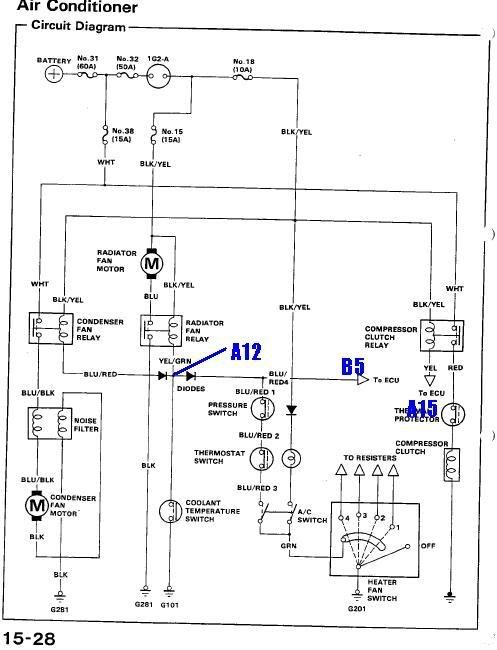
first pic below off of the Helm's Manual for 88-91 Civic the A12 connection is not drawn on the original diagram so i added a wire for it towards pin A12.
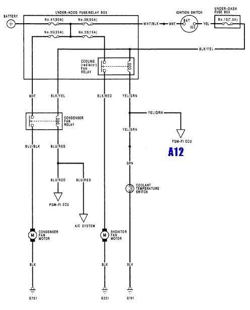
this diagram below for 92-95 Civic / Helms repair manual.
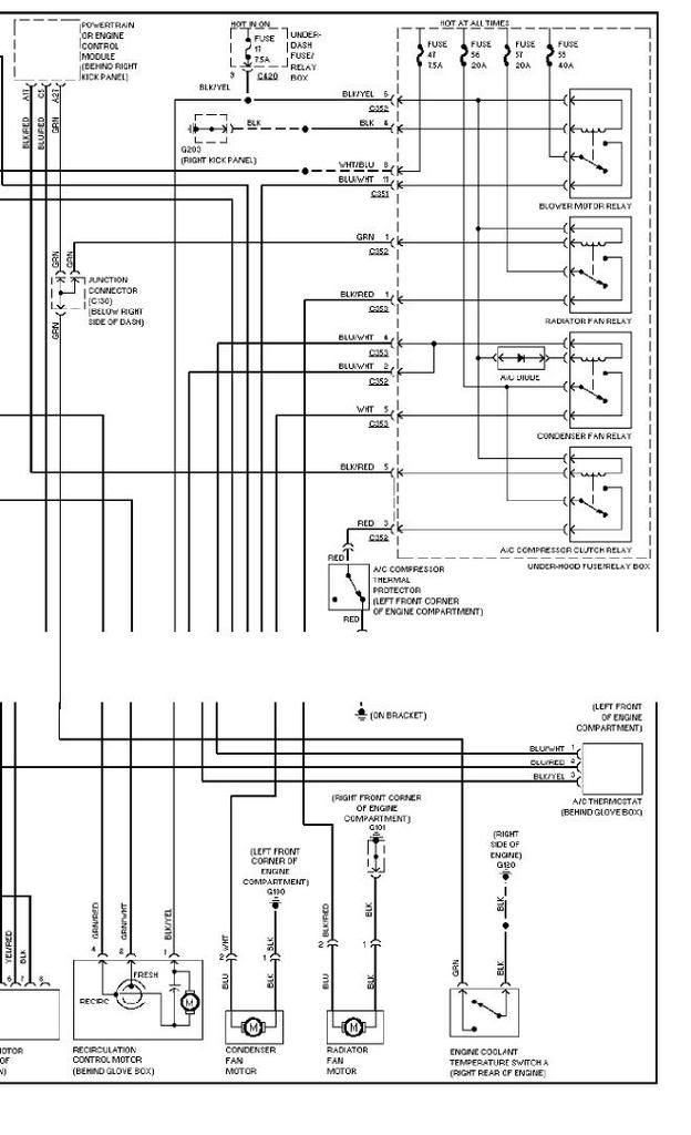
below diagram for 96-97 Civic, for OBD2A cars, FANC is pin A27.
Posted: Mon Jun 30, 2008 4:50 am
by Bindegal
See attached - my ECU-controlled-low-speed-fan-control addition.
The \"coil\" drawing below the relay is a 2-3 ohm big ass power resistor. /Allan
Posted: Mon Jun 30, 2008 5:07 am
by ef92b
Bindegal wrote:See attached - my ECU-controlled-low-speed-fan-control addition.
The "coil" drawing below the relay is a 2-3 ohm big ass power resistor. /Allan
nice mod! thanks for sharing.
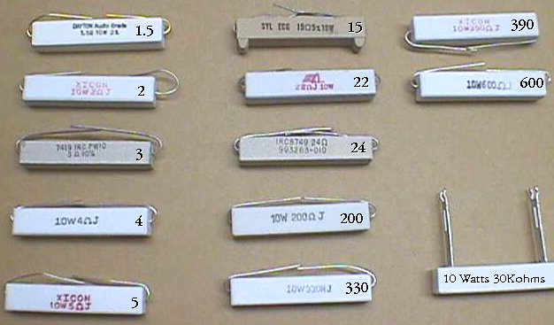
how many watts is that resistor? is it the ones in white rectangular packages such as these ones below?
Posted: Mon Jun 30, 2008 12:53 pm
by Bindegal
I think that depends on what kind of air flow you can get for the resistor. It has to dissipate a lot of watts. I used one in an aluminum housing that I could attach to the shock tower to help get rid of the heat. No problems so far. /Allan
Posted: Mon Jun 30, 2008 1:40 pm
by greasemonkee
I have a crankcase vacuum pump (really a GM smog pump) to pull fresh air through the crankcase that I did the same thing with. Since it would burn up and draw a lot of current to run continuously, I used the radiator control to operate the low speed so it doesn't come on until coolant temp = 80* F. That way it doesn't pull unnecessary load on the battery on a cold morning. The high speed is activated by GPO and engages at X rpm and load for wot operation only. The radiator fan is operated off another GPO that comes on at 400 rpm and cuts off over 60 mph. Everyhting is automatic now. Unfortunately all the aux outputs are used up. I bought this 2 ohm resistor from digikey - part# L100J2R0E-ND. This is a 100 watt long resistor, but stays within acceptable temp for a load that would otherwise pull 18 amps or so. The running amperage of the motor must be measured before determining the required resistance.
Posted: Mon Jun 30, 2008 2:22 pm
by Bindegal
Getting off-topic here..
Vacuum pump you say. So this could be used to pull fresh air through crankcase into an oilcatch tank? /Allan
Posted: Mon Jun 30, 2008 4:02 pm
by greasemonkee
Disclaimer: Offroad use only. Not for street use. Stock catch can with 1\" bung welded in, then dumped it into a K&N. I see about 3-3.5 in/hg. Nothing outstanding, but the oil smells like oil instead of gas now. The GPO feature gave it a more practical purpose, just be advised that startup of a big motor can make the afr twitch.