Serial Logging FJO WBO2 - constant AFR but voltage correct
Moderator: Gaskleppie
-
marshall.hagen
- Posts: 75
- http://phpbb3styles.net
- Joined: Wed Aug 05, 2009 1:31 pm
- Location: Starbucks, WA
Serial Logging FJO WBO2 - constant AFR but voltage correct
I am starting a new map from scratch and realized that the analog out from my FJO CWC0002 quit working, so I decided to try the serial logging option since I can still log AFR's using FJO's software. I figured out how to get eCtune to detect the COM and data stream, but it seems eCtune is not using the lookup table to convert the voltage to an AFR. While I'm driving, if I watch the 'data view' I can see the voltage in small font above the AFR. The AFR reads a constant 10.0, but the voltage is moving consistent with my WBO2 gauge. In the datalog attached, graph the O2 Voltage at the ECU. The voltage is correct; it reads 3.88v at closed throttle, and around 2.5-2.7v at cruising. It also dips down at tip-in & tip-out where my gauge shoots to 11.0-12.0 momentarily. (FJO uses a 0v-3.88v scale, not 0-5v). It seems as if there is an issue with either the lookup table, or ectune's access to the lookup table. Can someone verify my assessment and maybe Calvin can check out the code for the FJO serial logging to make sure it is correct... Thanks, Marshall
- Attachments
-
- 100904-1.elf
- Cruising Datalog
- (352.28 KiB) Downloaded 183 times
-
- 100904-itr.cal
- Calibration File
- (8.19 KiB) Downloaded 184 times
-
JaredKaragen

- Posts: 1504
- Joined: Fri Nov 23, 2007 4:00 am
- Location: Bay Area, Ca
- Contact:
-
marshall.hagen
- Posts: 75
- Joined: Wed Aug 05, 2009 1:31 pm
- Location: Starbucks, WA
So the channel 'O2 Voltage at ECU' was actually my 0-5v analog 'trying' to work again. I found out the reason why my analog quit working was because my ground wire broke (ground soldered into my ECU harness). The 0-5v signal returned when the USB/Serial adapter was plugged into the laptop via the FJO controller, completing a 'ground', although a weak one. I fixed the solder joint on my ground wire, but my 0-5v signal is fluctuating badly. My voltmeter measures a very consistent voltage coming from the FJO controller (+/- 0.01v at idle), but the ECU sees +/- 0.5v at idle. I have my FJO ground going directly to a primary ground on the ECU harness. I have heard of adding a resistor of some sort that bridges the ground and analog out wire (or something like that). Any tips on getting the voltage more consistent? Also, serial logging still does not work with the FJO. Calvin, will you have time to help debug this? Same situation as before: http://forum.ectune.com/viewtopic.php?t ... nd+voltage
-
marshall.hagen
- Posts: 75
- Joined: Wed Aug 05, 2009 1:31 pm
- Location: Starbucks, WA
Any tips on resolving the fluctuating analog signal? Clean signal from the controller, fluctuating signal when measured at the ECU... Calvin - Is there a way we can work on the serial logging option? Maybe we can do a remote desktop session.marshall.hagen wrote:I fixed the solder joint on my ground wire, but my 0-5v signal is fluctuating badly. My voltmeter measures a very consistent voltage coming from the FJO controller (+/- 0.01v at idle), but the ECU sees +/- 0.5v at idle.... Any tips on getting the voltage more consistent?
-
marshall.hagen
- Posts: 75
- Joined: Wed Aug 05, 2009 1:31 pm
- Location: Starbucks, WA
-
JaredKaragen
- Posts: 1504
- Joined: Fri Nov 23, 2007 4:00 am
- Location: Bay Area, Ca
- Contact:
What's the distance the analog out runs unshielded to the ecu? How far from the ecu plug is it soldered in? Is its shield to a ground wire or chassis ground? Is the analog out's ground (should have an independent ground) soldered to the ecu harness o2grou d within 2 inches of the ecu? There are many threads about voltage offsets; and this response touched on the basics of almost all of them.
95 Sol Si : D16z6 : TD04H-13C 74 Civic 1200 : 100% Stock
-
marshall.hagen
- Posts: 75
- Joined: Wed Aug 05, 2009 1:31 pm
- Location: Starbucks, WA
OK I spent all day today testing this setup. Frustration is setting in... I have four wires to the FJO box, a 12v swtiched power and ground, analog ground, and the 0-5v analog output. My 0-5v output terminates on an old ECU pin, so I can easily switch between D10/D12/D14 for debugging. I also kept enough of the copper wire exposed at the ECU plug so I can test the signal using a multimeter. I tried four different combinations of power/ground/analog ground, all with the same result. 1) 12v & ground directly to battery, analog ground alligator clipped to internal pin on ECU (D21). 2) 12v & ground directly to battery, analog ground soldered 2" from ECU on OBD1 harness (D22). 3) 12v & ground alligator clipped to inside of ECU (A25 & A23 respectively), analog ground alligator clipped inside ECU (D21). 4) 12v & ground alligator clipped to inside of ECU (A25 & A23 respectively), analog ground soldered 2" from ECU on OBD1 harness (D22). I did the above tests using D21 and D22, the two sensor grounds on the D-housing of my OBD1 harness. I also tried installing a 1N4001 Diode in-line with the sensor ground. For each of the setups above, I would measure the voltage at the wideband signal ECU pin and it would be constant voltage (+/- 0.01). Due to this, I do not think it is a shielding issue on the signal wire, because measured at the furthest point from the FJO controller the signal is very clean. eCtune would read +/- 0.5 - 0.8v, causing AFR readings to range from 11:1 - 15:1. It seems the 'top end' of the voltage fluctuation as shown in eCtune would be right around the same voltage I would measure using the multimeter at the signal wire. I found this thread and it mentions the Ostrich being very noisey... Of course I can't remove the Ostrich to test this or the car would die. Please suggest other things for me to test!JaredKaragen wrote:What's the distance the analog out runs unshielded to the ecu? How far from the ecu plug is it soldered in? Is its shield to a ground wire or chassis ground? Is the analog out's ground (should have an independent ground) soldered to the ecu harness o2grou d within 2 inches of the ecu? There are many threads about voltage offsets; and this response touched on the basics of almost all of them.
-
JaredKaragen
- Posts: 1504
- Joined: Fri Nov 23, 2007 4:00 am
- Location: Bay Area, Ca
- Contact:
Just a thought, try adding a ground for the ostrich, directly inside the ecu... I have an old 1.0 ostrich; with my JAW the minimum offset I saw was 3.45!!! It was very ridiculous. Maybe it may need some sort of filter circuit made to go between the FJO and ecu... There is a chance that it's failing/out of spec components in your oem ecu.... It had been in a car for how many years? Just a thought. Trying another ecu if available is a good thing to do. And also think about the analog out line; how far it runs unshielded to the ecu: the o2 is shielded from the ecu to the sensor plug.... Take that as a huge hint... If it's snaked through your dash, it could very well pick up noise from other wiring like a stereo or other prepherials. When I had a mad crazy offset; I just went with it and made adjustments to the map to smooth it out to fix the unevenness of the wb signal.
95 Sol Si : D16z6 : TD04H-13C 74 Civic 1200 : 100% Stock
-
marshall.hagen
- Posts: 75
- Joined: Wed Aug 05, 2009 1:31 pm
- Location: Starbucks, WA
Thank you for the reply. How would I go about adding a ground from the Ostrich-2 to the ECU board? I thought about testing another ECU... I'm sure I can get one locally to test. I remember installing a PLX Wideband on a Demon/eCtune setup last year, and the PLX instructions had a capacitor to install between the ground and analog out wire for noise filtering. I believe it was a 0.1uF (50v?) cap. I'll stop by radio shack on the way home today. I'll try a few of those things and report back. Thanks.
-
marshall.hagen
- Posts: 75
- Joined: Wed Aug 05, 2009 1:31 pm
- Location: Starbucks, WA
I added a 0.luF cap to between the analog ground and analog output. No difference. I found my old chipped ECU that quit working some time ago. I was using it to compare with the one I am using now. My old ECU is an OBD1 PR3 B16 ECU that I chipped myself using a Moates kit. This ECU read my wideband last year, but I got a solid CEL after I accidentally dropped it earlier this year and it hasn't worked since. My current ECU is an OBD1 P72 (P72-A01) that I bought off Craigslist a few years back already chipped. The picture below shows the area around the main chip socket. It is missing R54 from the board, and does not have R52 soldered in. Could this cause my problem? I have some socketing spares sitting around so I may go ahead and put in the resistor on R52 and test it tomorrow... I am still trying to find a working chipped ECU locally that I can borrow. 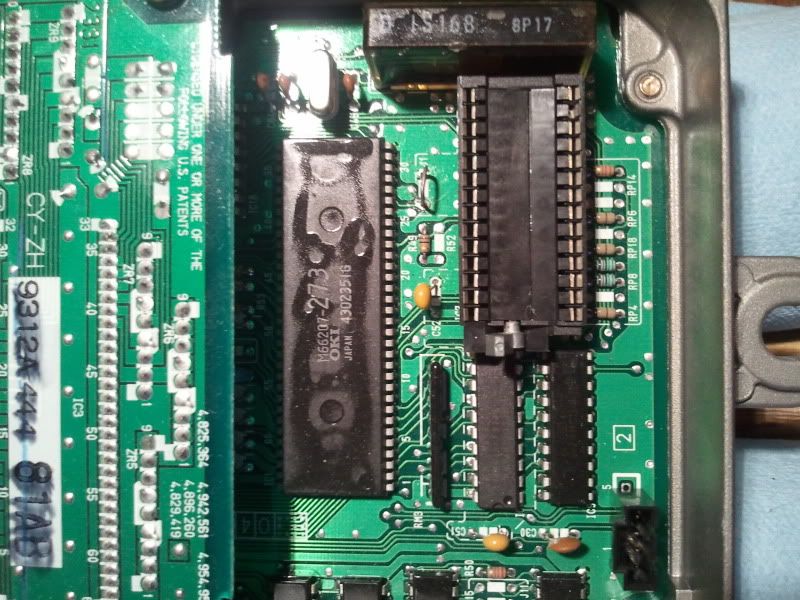
-
JaredKaragen
- Posts: 1504
- Joined: Fri Nov 23, 2007 4:00 am
- Location: Bay Area, Ca
- Contact:
Possibly; but probably not... you would have ECU errors (random CEL's, strange things). The ECU's power input circuit is close to the input lines them selves.... I wouldn't be surprised if some of the electrolytic caps on the board (which are how many years old being run how often?) are starting to fail... you often see the large capacitor explode and damage a lot of traces on the board when it goes... There is a mod to convert the o2 input to a 0-5v from the stock 0-3.3v(ish). There is a filter cap close by in the circuit between the ecu's input pin and the resistor(s) being removed/replaced. Lastly remember: Always shield as much of the o2 signal wire as possible to a good CHASSIS ground. The OEM harness does this well: literally about 2-4\" of unshielded wire between the ecu and sensor.... and that shielding is tied to a separate chassis ground. Hope it all helps.
95 Sol Si : D16z6 : TD04H-13C 74 Civic 1200 : 100% Stock
-
marshall.hagen
- Posts: 75
- Joined: Wed Aug 05, 2009 1:31 pm
- Location: Starbucks, WA
I really appreciate the help. The FJO analog output is actually a 0-3.5v, might have to do with it using the Honda NTK sensor. Back when I used my old PR3 on CROME, I was able to use D14 just fine (read with almost no offset). Since 3v on the FJO is 19:1 AFR, I've never had to do the 5v mod. On this P72 I'm using, I've tried D10 ELD / D12 EGR Lift / D14 O2. They all have the same voltage fluctuations. I'm starting to think my problem is with the P72 itself. Although, no other sensors seem to be acting up. This will be my next test - I'm still trying to hunt down an ECU to borrow for a day. The thing that keeps bothering me is that this whole setup worked before on CROME on my old ODB1 PR3 ECU. Same Ostrich-2, same wideband kit, same car. I understand what you are saying with the shielding. I guess I keep dismissing that as a problem because it has worked before with almost no offset, and if I probe the signal wire from the FJO using a multimeter (even when connected to the ECU) the voltage is very consistent. It is only the voltage read by eCtune in the software that is all messed up. I can literally watch the voltage on the miltimeter change by adding/reducing fuel, very consistent voltage +/- 0.01v. All the while eCtune is bouncing around +/- 0.5-0.8v.
-
JaredKaragen
- Posts: 1504
- Joined: Fri Nov 23, 2007 4:00 am
- Location: Bay Area, Ca
- Contact:
-
marshall.hagen
- Posts: 75
- Joined: Wed Aug 05, 2009 1:31 pm
- Location: Starbucks, WA
-
JaredKaragen
- Posts: 1504
- Joined: Fri Nov 23, 2007 4:00 am
- Location: Bay Area, Ca
- Contact:
For shuts and giggles: I found a bug some time ago, and it never really was found. Choose a wideband that has only two values for its slope in the table (lc1 has 2x of both values: which will work). Press save. Go back to the original setting and click save again. See if afr is still out of place on the logger. I ran into this issue while running a serial connection to my lc1. If my previously selected wideband was something like the narrowband; you would see the afr 'stick' on a value until it reached the next value on that scale... Kinda retarded but worth a shot.
95 Sol Si : D16z6 : TD04H-13C 74 Civic 1200 : 100% Stock